Hardware
Si5351 ShieldDDS Shield
Tx Shield
Rx Shield
Acorn II
A DDS on The Internet of Things
Applications
KeyerVFO
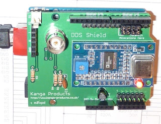
Arduino DDS Shield
"The m0xpd Arduino DDS shield provides a convenient interface between an AD9850 DDS module and an Arduino, opening up the benefits of this flexible “Electronics prototyping platform”. The shield makes the DDS Module easy to configure (through software) and to control (through familiar, everyday interfaces such as Keypads, Displays and Rotary Encoders)".
To understand your shield's hardware, take a look at the schematic...
The test program, running on an Arduino with the DDS Shield on top, sets up the system to produce a 1MHz output.
Your shield should draw around 90mA on the 5V supply from the host Arduino...
There's only one adjustment to make; the trim pot on the DDS module might need adjustment to get the shield's quadrature square wave outputs running.
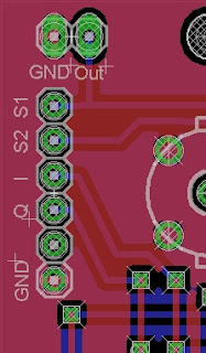
The square wave outputs are on pins 3 and 4 of the "RF Bus" connector, JP1.
Unfortunately, a manufacturing error on the board has mis-placed the labels for the pins - this is how the labels on the corner of the board SHOULD have looked...
With the test sketch above running, connect a 'scope to the sine wave outputs (on the BNC socket, the JP6 header or pins 1 & 2 of the RF Bus connector, JP1) and confirm the presence of the 1MHz sinewave.
Now look at the square wave outputs (pins 3 & 4 on JP1) and adjust the preset until the 250kHz square waves are running.
What if you don't have a 'scope?
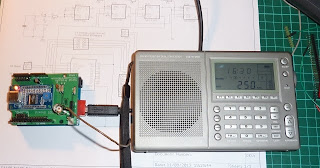
Put a short length of wire (10 cm or so) in the relevant pin of JP1 to act as an antenna. Place a receiver, in SSB mode, close to the wire and tune it to 250kHz (plus/minus an audio offset). You'll soon know if there's a square wave there!
Applications
Iambic Keyer for Arduino
Those new to Arduino will find this application a little more instructive than the usual "push a button and light an LED" example - and it might be useful in the shack!
All my keyers support both a straight key and a paddle - as I find it easier to switch to the straight key to change speed or to send a long "dah" for zero, etc.
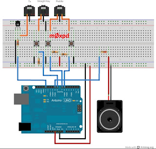
This is how you need to hook up the Arduino...
For those who find the Fritzing representation above too naive to be useful, here's a real schematic...
I've shown switches in the schematic - these represent the switch elements in your key or paddle which are just SPST switches.
Arduino code for the keyer is available here.
Note that the later "Occam's Microcontroller" rigs have not just integral keyers but also automated CQ calls - you can find the code here.
Kanga VFO
The m0xpd Arduino VFO system demonstrates use of hardware elements available from Kanga, combining an Arduino (UNO or MEGA), a DDS Module and a display into a system that is both instructive (delving a little deeper into the possibilities of Arduino) and practically useful (you end up with a decent VFO!)...
The schematic is shown below...
An Eagle schematic file is available here. (Note - there is no board design, nor any intention to produce one)
The Arduino code for the VFO is available here . You should ensure you have the correct libraries (including a library for the LCD display consistent with the generation of Arduino Development Environment you're using), available from here.
Enhanced Kanga VFO
To coincide with the appearance of the new Kanga / m0xpd DDS Shield, I've put together a second VFO system.
This system is much more advanced than the simpler VFO described above - not just in functionality, but also in hardware...
As well as use of the DDS Shield, the new VFO exploits an I2C interface for the LCD display unit to save on the load on Arduino pins, freeing up some pins to use to support input push-buttons. If you intend to use the display from Kanga UK, you'll find the appropriate software library at this page. If you're using other displays, you must source your own library appropriate to that hardware.
The VFO has three controls; a rotary encoder (with integral push button), used for frequency (and other parameter) inputs and access to the menu system and two push-buttons, used (in normal mode) to change the "speed" of frequency input (the rotary encoder can change frequency in steps of 1, 10, 100 ... 1 MHz) and (in menu mode) to move between the (4) menu categories.
The system supports the amateur bands between 136 kHz and 10m and also offers a continuous "signal generator" mode. There are programmable offsets for each of the five modes (CW, CW(R), AM, LSB and USB) and continuously variable Receive Incremental Tuning (/"Clarifier"). The system can support additive offsets to accommodate an IF stage and has two memories ("VFO A & B"). A hardware input switches between "Receive" and "Transmit" modes.
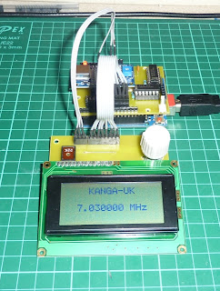
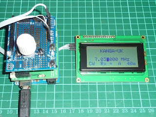
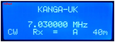
The system is seen in "Normal" operating mode here...
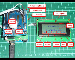
As you can see, it is made from a stack of Arduino, DDS Shield, Prototyping Shield and an LCD Display (with I2C interface), all of which are available from Kanga UK. Of course, you don't need to use the DDS Shield or the Prototyping board - but it sure makes things simpler! If you're building the VFO into anything more permanent than the experiment described here, you'll certainly want to drop the prototyping shield and mount the rotary encoder, pushbuttons and display into the wall of your enclosure.
In "Normal" operation, the display shows the frequency selected, the mode, the Receive / Transmit status, the RIT offset (above, equal or below the default value for the mode), the VFO selected (A or B) and the band.
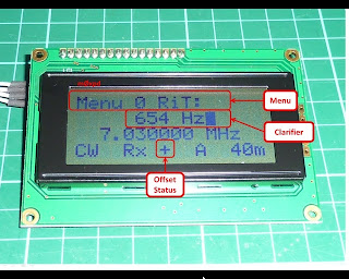
In "Menu" operation, the display format changes - here, for example is the display in Menu 0 (RIT)...
where the RIT value is shown as it is continuously varied. Notice that the "Clarifier" is set above the default 600Hz offset - so the offset status indicator has changed form "=" to "+".
The Arduino code for the enhanced VFO is available here and a schematic of the user interface components is shown below...
[A previous version of this schematic showed the rotary encoder's push-button erroneously connected to A0. Apologies to all those (including Dennis, g6ybc) who were inconvenienced by my mistake.]
The VFO is shown above running on an Arduino UNO. It will run on the Arduino MEGA 2560 boards available from Kanga-UK but in this case the display must be connected to the SCK and SDA pins (which are not shared with A4 and A5 on the MEGA).
A further enhancement of the Kanga VFO code has been produced to support the newly available 20*4 backlit LCD...
The code (which will support both the 20*4 and 16*4 display formats) is available here .
Kanga / m0xpd Receiver Shield
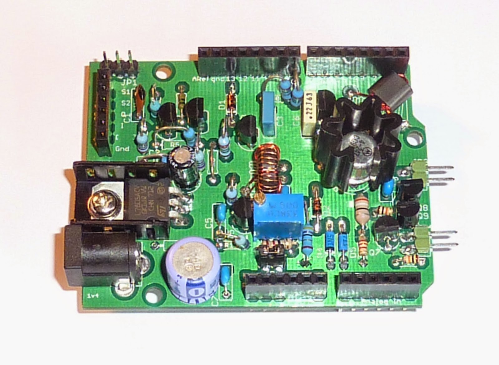
The Kanga / m0xpd Receiver Shield is a simple, Direct Conversion receiver system for the low HF bands...
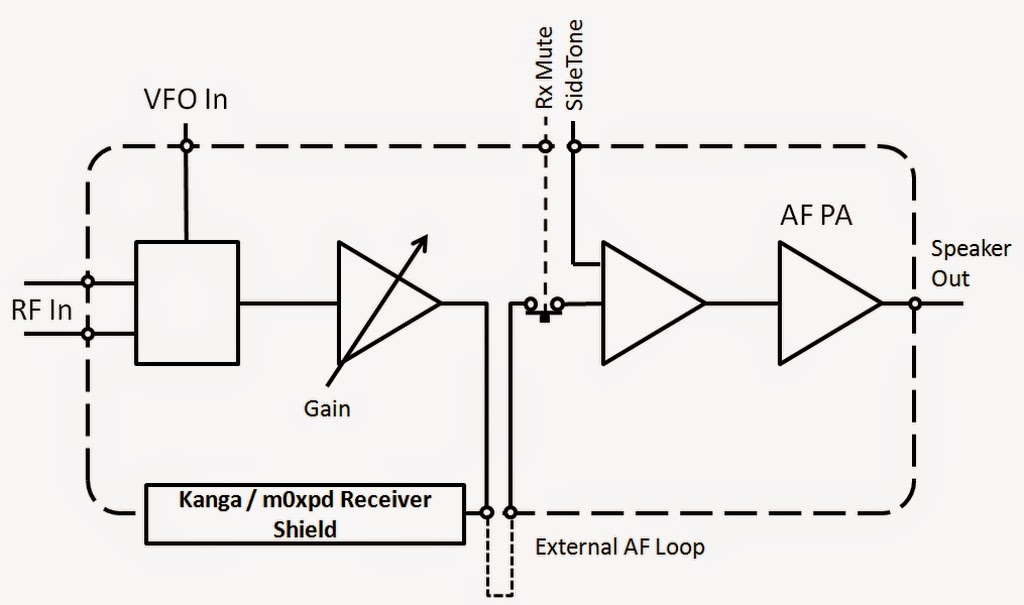
The Rx Shield uses a 602/612 Gilbert Cell Mixer, followed by a two-stage audio path which supports limited on-board filtering, an off-board send/return loop (in which the user can add volume control, further filtering or processing, etc), on-board Rx muting, and a level control. There is an on-board (LM386) amplifier, which will easily drive low impedance headphones or a speaker.
The structure of the system is shown here...
The "VFO" input is applied at the "Spare" input on the m0xpd RF bus (if used with a Tx Shield and a Kanga / m0xpd RF generator shield, this signal routing will be implemented automatically).
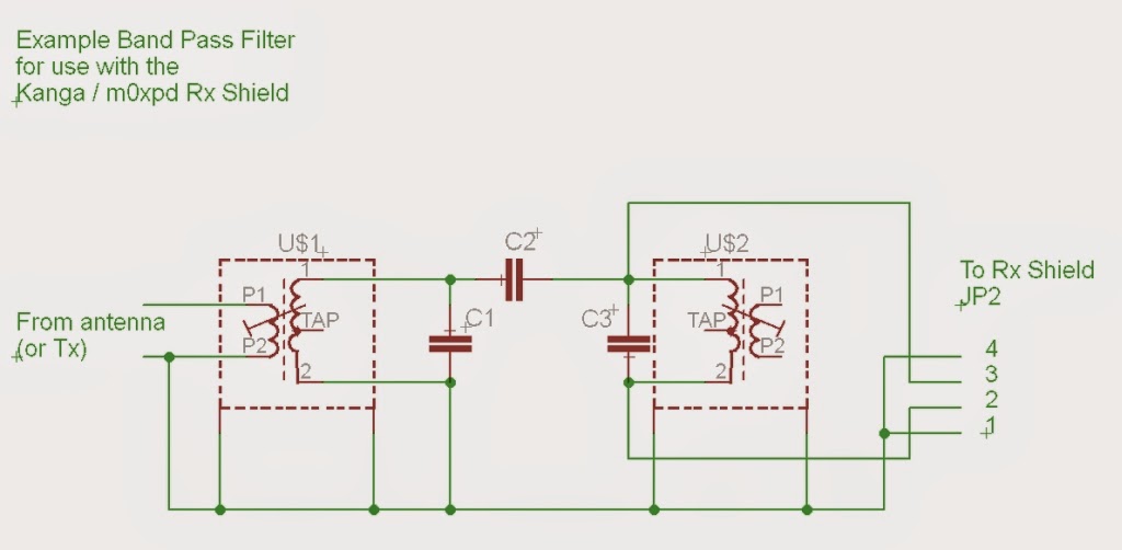
The receiver must be used with a band-pass filter, appropriate to the band of interest. The filter design is shown in the following schematic...
The external loop must preserve the dc “biasing” of the audio signal in order to the Rx mute to work, so a simple way to implement a volume control is suggested in the figure below, in which a potentiometer, configured as an ordinary potential divider, is grounded not to “ground” but to an “ac ground”, provided by a large capacitor.
The shield's audio path has been provided with limited on-board filtering, to give frequency response as shown...
Rx muting is achieved by pulling the Rx mute line to ground - this is usually connected to Arduino pin D10 (which is used for this purpose in the "Occam's" software).
This receiver developed from an ancestor within the Occam's Microcontroller project - you will find the code developed for that project here.
Kanga / m0xpd Transmitter Shield
The Kanga / m0xpd Transmitter Shield is a simple, Direct Conversion transmitter system for the low HF bands, based on grjv's "Sudden"...
The transmitter was originally developed to operate CW (and can easily form a complete CW transceiver system with an Arduino, an RF Generator board, such as the DDS Shield and an Rx Shield). However, it has also been used as a beacon transmitter in various other beacon and digital modes and as a DSB transmitter.
It will generate approximately 1.5W on the low HF bands.
The shield includes an RF buffer / driver circuit to feed the VFO signal to the Rx Shield, a keying stage and a 5V power regulator, in addition to the RF power amplifier (although use of the 5V power regulator is recommended only to power a DDS Module, rather than an Arduino).
You must use the transmitter with an appropriate output filter - appropriate designs can be found on the G-QRP website.
As with the receiver shield, this transmitter is related to the Occam's Microcontroller project - you will find the code developed for that project here.
Kanga / m0xpd Si5351 Shield
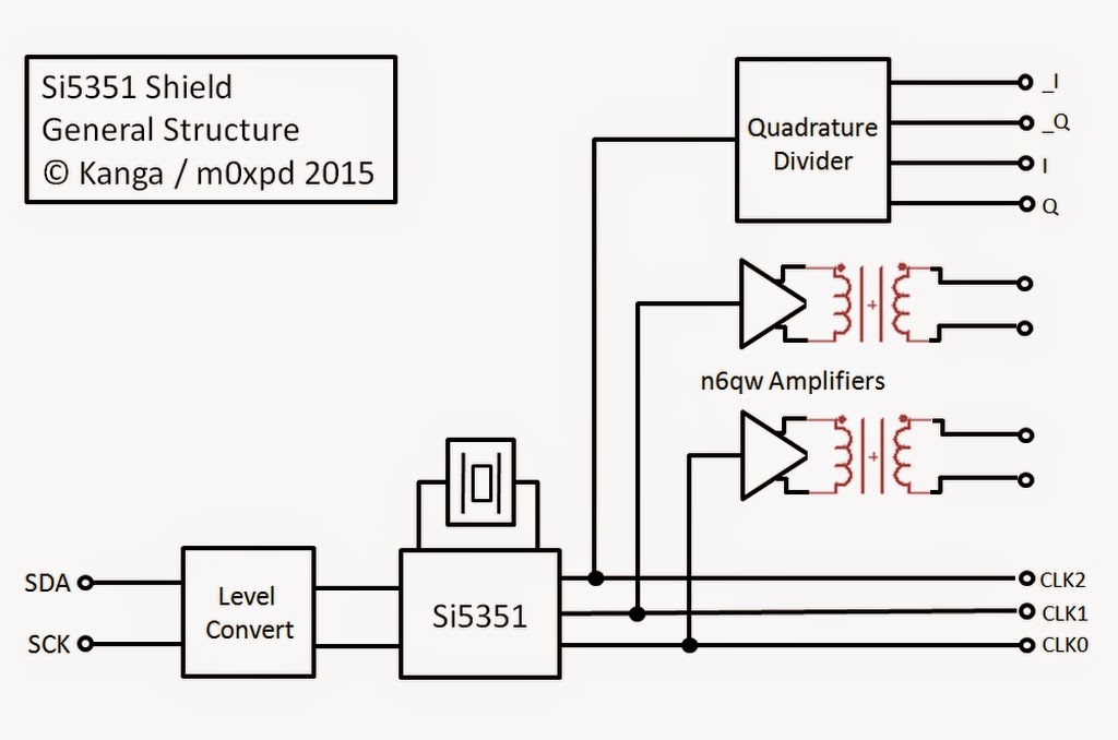
The Kanga / m0xpd Si5351 Shield is a flexible, 3-channel RF generator sub-system, partnering the Silicon Labs Si5351 Device with a pair of broadband amplifiers and a quadrature divider.
It is presented as an Arduino “Shield”, but it may also be operated in any other environment capable of providing the necessary I2C control signals (such as the Raspberry Pi, where it has been successfully operated).
General structure of the shield is shown here...
The Shield uses the Silicon Labs Si5351 I2C configurable clock generator to provide three independently programmable RF sources up to c. 160 MHz All three of these signals are available on an expanded implementation of the m0xpd RF Bus (which retains full backward compatibility with the original m0xpd RF bus, introduced on the DDS Shield allowing this Shield to be used with the Kanga m0xpd Tx Shield and Rx Shield).
Two channels are further amplified by variable gain, broadband amplifiers with isolated outputs, capable of driving 50 Ohm loads.
The third channel is further passed to a quadrature divider, which derives quadrature square waves at a quarter of the clock frequency, suitable for the implementation of “Tayloe” detectors in SDR schemes. These quadrature clocks (and their complements) are available on the expanded m0xpd RF Bus.
The system can be controlled by 3v3 or 5v logic signals, with the logic level selected by the voltage applied to the IOREF pin. On an Arduino application, this will be generated automatically by the host board. In any other application, the user must apply the appropriate voltage to this pin.
The system requires 3V3 for the “digital” subsystem and a nominal 12V for the amplifiers. In standard Arduino-based applications, the 3V3 supply is derived from the host Arduino board. The analogue power can be supplied from the Arduino “VIn” power or from a separate d.c. power supply (sharing common ground reference). In other applications, 3V3 power must be supplied to the board. No on-board regulation is provided.
Test software to support the shield can be downloaded from here and the shield will support all the Si5351 applications given on the Shack Nasties blog, such as the modified version of the "Occam's" rig.
Acorn II Software Defined Radio
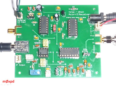
The Kanga / m0xpd Acorn II SDR Receiver is an upgraded version of the earlier G0NQE Acorn SDR receiver. It is presented as a 40m receiver kit, capable of operation on other bands with off-board filters, with two options for frequency control: an on-board crystal or input from an external oscillator.
This external control can be achieved using any suitable stable RF source, which is applied through the external oscillator input of the Acorn II. Particularly suitable is the m0xpd Si5351A Shield, also available from Kanga Products.
A simple Arduino sketch to configure the Si5351 to generate two local oscillator signals is available here. The user can set these frequencies to any values, achieving flexible configuration of the receiver, by simply entering the desired oscillator settings into the Arduino Development Environment...
A more elaborate, adjustable program, in which the oscillator is continuously variable through (e.g.) a Rotary Encoder, is easily developed using the methods described in the VFO. Such a program was described here.
A public release of such an adjustable program may be made available at a later date - watch this space.
Back to top
A DDS on The Internet of Things
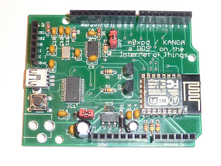
The m0xpd / Kanga ESP8266 - AD9834 board 'A DDS on The Internet of Things' combines Espressif System's ESP8266 system-on-chip (in an AI-Thinker ESP-12 Module) and Analog Device's AD9834 Direct Digital Synthesizer, in an attempt to encourage experimentation and activity on the boundary between the Internet of Things and Amateur Radio.
Support for this board is provided on this site.
Back to top
----------------------------------------------------













I have complete set of parts and boards from Kanga, build dds shield and wired up display using I2C as in your notes. Clicked on sketch link and went to GIST site, downloaded and untazed the file but there is no extension on file. I then copied text from file and pasted in programmer got lots of errors
ReplyDeleteThis report would have more information with
"Show verbose output during compilation"
enabled in File > Preferences.
Arduino: 1.0.5-r2 (Windows NT (unknown)), Board: "Arduino Uno"
sketch_feb25a:159: error: 'LiquidCrystal_I2C' does not name a type
sketch_feb25a.ino: In function 'void setup()':
sketch_feb25a:165: error: 'lcd' was not declared in this scope
sketch_feb25a.ino: In function 'void LCD_Display_Freq(double)':
sketch_feb25a:395: error: 'lcd' was not declared in this scope
sketch_feb25a.ino: In function 'void LCD_Display_RiT(int)':
sketch_feb25a:410: error: 'lcd' was not declared in this scope
sketch_feb25a.ino: In function 'void LCD_Clear_RiT()':
sketch_feb25a:417: error: 'lcd' was not declared in this scope
sketch_feb25a.ino: In function 'void LCD_String_Display(int, int, char*)':
sketch_feb25a:423: error: 'lcd' was not declared in this scope
sketch_feb25a.ino: In function 'void LCD_Int_Display(int, int, int)':
sketch_feb25a:428: error: 'lcd' was not declared in this scope
sketch_feb25a.ino: In function 'void LCD_Char_Display(int, int, char)':
sketch_feb25a:433: error: 'lcd' was not declared in this scope
sketch_feb25a.ino: In function 'void setTxDisplay()':
sketch_feb25a:473: error: 'lcd' was not declared in this scope
Tim
DeleteIt sounds as if you either a) do not have the correct LCD library installed (there is a copy of it on the Occam's Microcontroller Software page: https://sites.google.com/site/occamsmicrocontroller/home/software )
or b) there is some problem with the installation of that library on your system.
I had similar errors before installing the LiquidCrystal_I2C library but all ok after installation. .... Except that the display reads 'MHzz' after the value [Cont mode] unless I'm on 10.000000 in which case it moves right and reads 'MHz' ...... then 9.999999 moves left and reads MHzz again. I'm trying to spot a fix but you may already have done this? Nice application BTW.
ReplyDeleteRichard
DeleteSorry - hadn't spotted this. Can you try adding a space after MHz (inside the inverted commas) in the function call to lcd.print in LCD_Display_Freq() (the first of the subroutines - easy to find). Like this: lcd.print(" MHz ");
Let me know if it works.
That seems ok. Still does the shift right-left but does maintain 'MHz'. Thank you.
ReplyDeleteGreat - can you tell me which program we're talking about - and from where you downloaded it.
DeleteI'll fix the source.
I'll keep a closer eye on this comment .... not sure the previous one got there.
ReplyDeleteCan I alter the values 4294967295/125000000 to shift the frequency slightly? I guess that the first part is the maximum division ratio and the second value the TCO frequency?
Ok ... previous comment didn't go properly. It said that the code came from the link on this page to GitHub Gist m0xpd / Kanga VFO 2 [see line 400].
ReplyDeleteAlso, similar extra z or zz when RIT reduced .... not a big issue.
Also seem to be 0.001% low in frequency compared to my frequency counters .... which may need checking!!
Richard
DeletePlease can you contact me by email (see QRZ.com).
We'll deal with this outside the "comment" framework and then share outcomes publicly.
OK ... last comment .... guess my TCO is running a bit slow .... changed 125000000 to 124998750 to get the o/p frequency in line with my counters. Off-air standard for me next then ??
ReplyDeletehello dear friend i am 9a3xz .what things are included arduino dds shield m0xpd from Kanga - uk ?
ReplyDeletethanks in advance
Mikele
DeleteI can't speak for Kanga - you should check out the shield directly on their website (the address is: http://www.kanga-products.co.uk/index.php?option=com_content&view=article&id=88&Itemid=99).
However - unofficially - I know that their kit includes all the hardware (including the DDS module and all the connectors) you need to complete the shield.
Paul,
ReplyDeleteI've got a set up that uses the dds shield tx & rx and have trouble with the encoder. The problem is that the encoder only work (erratically) one way. The push button switches are also a little erratic. Is this something you've come across?
Alex
ReplyDeleteThe Kanga DDS Shield example applications interfaced to the Rotary encoder using hardware polling - to make the software simple for newcomers to digital applications.
This can result in less-than-perfect operation of the rotary encoder (but should not leave it working only in one direction) - the alternative "interrupt" interface is described here:
http://m0xpd.blogspot.co.uk/2014/12/continual-interruptions.html
Given you report problems with the push buttons (which I have not experienced), I think you have must other issues. Are you sure you have pull-up resistors present (externally or internally)?